Product Overview
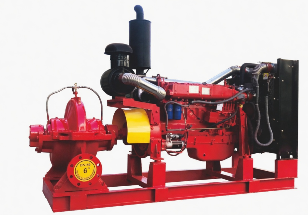
The XBC Series Diesel Engine Fire Pump Set is designed to provide dependable emergency water supply for fire protection systems when the main electrical power supply or electric fire pump is unavailable.
Developed in accordance with GB 6245-2006 requirements for fire pumps, the unit combines a diesel engine, fire pump, control system, cooling system, fuel system, batteries and related accessories on an integrated common base.
When a fire signal, pressure-loss signal or power-failure condition is detected, the diesel engine control system can initiate the starting sequence and drive the fire pump to deliver water to the connected fire protection network.
Depending on regional and project terminology, this product may also be referred to as an XBC Diesel Fire Pump Set, Diesel Engine-Driven Fire Pump, Diesel Fire Fighting Pump Set, Emergency Diesel Fire Pump Unit or Engine-Driven Fire Pump Package.
The XBC Series can be matched with a horizontal single-stage fire pump, horizontal split-case double-suction fire pump or horizontal multistage fire pump. The final pump type, diesel engine power and control configuration are selected according to the required flow, pressure and project operating conditions.
Key Features
- Independent diesel engine drive for emergency fire-water supply
- Manual, automatic and emergency manual starting modes
- Automatic starting sequence with up to three start attempts
- Start-failure alarm when the engine does not start after the programmed attempts
- Reliable starting performance and strong overload capacity
- Compact common-base arrangement for convenient installation
- Automatic monitoring of engine and pump operating conditions
- Status indication for starting, operation, shutdown and battery charging
- Alarm protection for abnormal pressure, temperature, speed and battery conditions
- Automatic battery-charging function
- Optional standby battery circuit
- Optional automatic periodic test function
- Adjustable pump performance through mechanical or electronic speed control
- Optional cooling-water preheating for low-temperature environments
- Convenient inspection, operation and routine maintenance
- Configurable for different pump types and fire-water duty points
Applications
The XBC Series Diesel Engine Fire Pump Set is suitable for emergency and standby fire-water supply applications, including:
- Fire hydrant systems
- Automatic sprinkler systems
- Water-spray fire extinguishing systems
- Industrial fire-water networks
- Commercial building fire protection
- Residential building fire protection
- Hotels and hospitality facilities
- Office buildings
- Warehouses and logistics facilities
- Manufacturing plants
- Hospitals and medical facilities
- Mining facilities
- Municipal fire-water stations
- Infrastructure and public-service projects
It is particularly suitable for projects where fire-water supply must remain available during electrical power failure or when the electric fire pump cannot operate normally.
Customer Benefits
Independent Emergency Water Supply
The diesel engine provides a power source independent of the main electrical system. This helps maintain fire-water delivery when the site power supply fails or the electric fire pump is unavailable.
Automatic Emergency Response
The automatic control system can receive fire, pressure or power-failure signals and initiate the diesel engine starting sequence without relying entirely on manual intervention.
Improved Starting Reliability
The controller can perform up to three automatic start attempts. If the unit does not start successfully, the system issues a start-failure alarm so that operating personnel can respond promptly.
Flexible Pump Matching
The diesel engine unit can be matched with different fire pump structures, allowing the system to be selected according to the required flow, pressure, installation arrangement and project conditions.
Simplified System Integration
The diesel engine, pump, controller, cooling system, fuel system, batteries and accessories can be supplied as an integrated fire pump unit, reducing the amount of on-site equipment matching and assembly work.
Clear Operating Monitoring
Operating status, battery charging and abnormal conditions can be indicated through the control system, supporting routine inspection and emergency fault identification.
Convenient Maintenance
The compact common-base structure and accessible components support regular inspection, testing, servicing and replacement of consumable parts.
Technical Specifications
Main Technical Parameters
| Product Series | XBC Series |
| Product Type | Diesel engine-driven fire pump set |
| Standard Basis | Developed in accordance with GB 6245-2006 for fire pumps |
| Diesel Engine Speed | 1450-2900 r/min |
| Starting Modes | Manual start, automatic start and emergency manual start |
| Automatic Start Attempts | Up to three programmed attempts |
| Starting Time | Approximately 5, 10 or 15 seconds to rated speed, depending on unit capacity and configuration |
| Ambient Atmospheric Pressure | Above 90 kPa |
| Ambient Temperature | 5°C to 40°C under standard operating conditions |
| Relative Humidity | Not more than 80% |
| Cooling Method | Closed-loop forced water circulation as standard |
| Optional Cooling Method | Open-loop water circulation, subject to project confirmation |
| Low-Temperature Option | AC 220 V cooling-water preheater |
| Battery System | Starting battery with automatic charging; standby battery circuit available as an option |
| Control Functions | Manual control, automatic control, status indication, operating monitoring and alarm protection |
| Flow and Pressure | Determined according to the selected fire pump model and project duty point |
Available Pump Types:
- Horizontal single-stage fire pump
- Horizontal split-case double-suction fire pump
- Horizontal multistage fire pump
Model Designation
A typical model designation may be expressed as:
XBC 10.0 / 160G – CDS
- XBC: Diesel engine fire pump set
- 10.0: Outlet pressure expressed as MPa × 10
- 160G: Rated flow expressed in L/s
- CDS: Pump type designation
Available pump-type designations depend on the selected horizontal single-stage, split-case double-suction or horizontal multistage fire pump configuration.
Operating Principle
The XBC Diesel Engine Fire Pump Set can operate as part of an automatic fire-water supply system together with an electric fire pump, jockey pump and fire control centre.
When the diesel fire pump controller receives a start command caused by a fire signal, pressure reduction, electrical power failure or electric-pump fault, the controller energizes the starting circuit.
The starter motor begins cranking the diesel engine, the fuel control mechanism opens, and the engine accelerates gradually to its rated operating speed. During operation, the control system monitors the principal engine and pump parameters.
If the first starting attempt is unsuccessful, the controller can repeat the starting sequence. After the programmed number of unsuccessful attempts, the system issues a start-failure alarm.
When the fire signal is removed, system pressure is restored, or the normal electrical system and electric fire pump return to service, the diesel fire pump can enter a delayed shutdown sequence according to the control configuration.
The exact automatic-start, switching and shutdown logic should be confirmed according to the selected controller and the requirements of the fire protection system.
Control, Indication and Alarm Functions
Available indication functions may include:
- Ready-to-start status
- Manual-start status
- Automatic-start status
- Engine-running status
- Engine-shutdown status
- Battery-charging status
- Overspeed indication
- Low lubricating-oil pressure indication
- High engine-water-temperature indication
- Low battery-voltage indication
- Low fuel-level indication
- Low cooling-water-level indication
Available alarm and protection functions may include:
- Repeated start-failure alarm
- Overspeed alarm or protection
- Low lubricating-oil pressure alarm or protection
- High cooling-water-temperature alarm or protection
- High lubricating-oil-temperature alarm or protection
- Automatic battery-charger fault alarm
- Low battery-voltage alarm
- Low battery-charging voltage alarm
- Low fuel-level alarm
- Low cooling-water-level alarm
The final indication, alarm and protection functions depend on the selected controller and project configuration.
Cooling System and Low-Temperature Operation
The standard diesel engine cooling arrangement uses a closed-loop forced water-circulation system. The cooling system may include a water tank, fan, water pump, thermostat, air guide and expansion components.
The system is designed to remove heat generated during engine operation and maintain an appropriate operating temperature.
An open-loop cooling arrangement can also be considered where project conditions require cooling water to circulate between the fire-water system and the diesel engine through a heat exchanger.
For environments below 5°C, an optional AC 220 V cooling-water preheater can be installed to support normal starting and operation.
For operation below 0°C, the instruction manual recommends an antifreeze mixture of approximately 40% ethylene glycol and 60% clean water, providing a freezing point of approximately -22°C. The final antifreeze selection should also follow the diesel engine manufacturer’s requirements and local environmental conditions.
Performance Data and Drawings
The final performance data should be selected according to the required flow, outlet pressure, pump type, diesel engine power and operating environment.
- Fire pump performance table
- Flow and pressure performance curve
- Diesel engine technical data
- Diesel engine power-correction information
- Fuel-tank capacity selection table
- Overall arrangement drawing
- Common-base drawing
- Foundation and mounting drawing
- Inlet and outlet connection dimensions
- Cooling-system information
- Control-system schematic
- Mechanical speed-control schematic
- Electronic speed-control schematic
- Project-specific technical datasheet
The manual includes arrangement drawings for several XBC configurations, including horizontal single-stage, horizontal multistage and horizontal split-case fire pump sets.
Actual dimensions, performance curves and technical drawings should be confirmed according to the selected model before manufacturing and installation.
Selection Guidance
To select the appropriate XBC Series Diesel Engine Fire Pump Set, please provide the following project information:
- Required flow rate
- Required outlet pressure or pump head
- Required fire pump type
- Fire-water system type
- Minimum and maximum operating pressure
- Site altitude
- Minimum and maximum ambient temperature
- Relative humidity
- Available pump-room dimensions
- Pipeline inlet and outlet sizes
- Preferred diesel engine speed
- Required starting and control method
- Required automatic-start signal
- Required alarm and monitoring functions
- Battery and standby-battery requirements
- Cooling-system requirements
- Low-temperature preheating requirements
- Fuel-tank operating-time requirement
- Exhaust-system conditions
- Local electrical supply for the controller and auxiliary equipment
- Required technical standard or project specification
Diesel engine output can be affected by altitude and ambient temperature. Where site conditions differ from the standard operating range, the engine power should be corrected and matched with an appropriate safety margin.
The final pump, diesel engine, controller, cooling system and accessory configuration should be confirmed according to the actual duty point and site conditions.
Installation and Maintenance
Installation Requirements
Adequate access space should be reserved around the diesel engine fire pump set for ventilation, heat dissipation, lifting, inspection and maintenance.
The pump-room height should accommodate the equipment height and lifting requirements. The room should also provide sufficient ventilation openings to prevent hot discharged air from circulating back into the diesel engine cooling system.
The equipment foundation should have adequate strength and stiffness to support the unit and absorb operating vibration.
The common base should be installed level, and the pump and diesel engine shaft alignment should be inspected after installation and pipeline connection.
Connected pipelines should be supported independently. Pipeline weight and external stress should not be transferred directly to the fire pump.
The exhaust pipeline should be properly supported, insulated where necessary and routed outdoors. Excessive pipe length, sharp bends and unnecessary elbows should be avoided.
The fuel system should be installed according to the selected diesel engine and fuel-tank arrangement. The fuel tank should provide sufficient operating time for the project requirement and should be positioned away from major heat sources and electrical equipment.
The control cabinet should not be installed directly in front of the diesel engine radiator or cooling-air outlet. It should be positioned where operation and inspection are convenient.
Pre-Start Inspection
Before starting the fire pump set, check:
- Pump rotation direction
- Inlet and outlet valve positions
- Pump and pipeline condition
- Diesel engine lubricating-oil level
- Cooling-water level
- Fuel level
- Battery voltage and connection
- Starting circuit
- Control-cabinet operating mode
- Shaft alignment
- Coupling condition
- Alarm and protection functions
- Cooling and exhaust systems
- Leakage at pipelines and connections
The pump should not be operated without water. Where a cooling-water preheater is installed, the cooling system should contain sufficient water before the heater is energized.
Manual Operation
For manual starting, place the controller in manual mode and press the start control.
After the engine starts, verify lubricating-oil pressure, cooling-water temperature, pump pressure, shaft condition and operating sound.
The engine should be accelerated gradually to the required operating speed. During operation, the pump and diesel engine should be observed for abnormal vibration, leakage, noise or temperature rise.
For manual shutdown, close or adjust the system as required and stop the diesel engine according to the controller operating procedure.
Automatic Operation
For automatic operation, place the controller in automatic mode.
When the controller receives the configured fire, pressure-loss or power-failure start signal, it begins the programmed starting sequence.
Automatic-start delay, repeated-start logic and shutdown conditions depend on the selected controller and project control design.
Routine Maintenance
The fire pump set should be test-run at least once every 15 days.
Each test run should last not less than 15 minutes so that the diesel engine fire pump remains in a suitable standby condition.
- Checking the pump-shaft seal
- Inspecting whether adjustment or replacement is required
- Adding lubricating oil or grease at the specified intervals
- Checking engine lubricating oil
- Checking cooling water and antifreeze
- Checking fuel level and fuel-system condition
- Checking battery voltage and charger operation
- Checking cooling-water temperature
- Checking lubricating-oil pressure
- Checking control instruments and alarm functions
- Recording start time, running time and test results
If the fire pump set will remain out of service for a long period, cooling water should be drained where freezing is possible, and the unit should be protected according to the pump and diesel engine maintenance instructions.
Available Configurations
- Horizontal single-stage fire pump
- Horizontal split-case double-suction fire pump
- Horizontal multistage fire pump
- Different rated flow and pressure duty points
- Diesel engine speeds from 1450 to 2900 r/min
- Mechanical speed control
- Electronic speed control
- Manual and automatic control systems
- Emergency manual starting arrangement
- Single or dual starting-battery systems
- Automatic battery charger
- Automatic periodic test function
- Closed-loop cooling system
- Open-loop cooling arrangement
- Cooling-water preheater
- Fuel system and project-sized fuel tank
- Exhaust silencer and exhaust piping
- Common base
- Cooling-water tank
- Matching valves, pipelines and instruments
- Customized nameplate, connection and packaging requirements
Optional functions and accessories should be confirmed according to the selected model, controller and project requirements.
FAQs
What is an XBC Series Diesel Engine Fire Pump Set?
The XBC Series is an integrated fire pump unit driven by a diesel engine. It is designed to provide emergency fire-water supply when the main power supply or electric fire pump is unavailable.
What other names are used for this product?
International projects may use terms such as Diesel Fire Pump Set, Diesel Engine-Driven Fire Pump, Diesel Fire Fighting Pump Set, Emergency Diesel Fire Pump Unit or Engine-Driven Fire Pump Package.
How does the diesel fire pump start automatically?
The controller receives a fire, pressure-loss, power-failure or electric-pump fault signal and activates the starting circuit. The starter motor cranks the engine, and the control system monitors the starting and operating process.
How many starting methods are available?
The unit supports manual start, automatic start and emergency manual start.
What happens if the diesel engine does not start?
The automatic controller can perform up to three starting attempts. If the engine still does not start, the system issues a start-failure alarm.
Which fire pumps can be matched with the XBC diesel engine unit?
The unit can be matched with a horizontal single-stage fire pump, horizontal split-case double-suction fire pump or horizontal multistage fire pump.
Can the pump flow and pressure be adjusted?
The operating performance can be adjusted within the permitted range through mechanical or electronic diesel-engine speed control. Final flow and pressure must be confirmed according to the selected pump model.
Can the unit operate in cold environments?
A cooling-water preheater is available for low-temperature environments. Antifreeze may also be required below 0°C according to the diesel engine manual and project conditions.
How often should the diesel fire pump be tested?
The manual recommends a test run at least once every 15 days, with each test lasting not less than 15 minutes.
What information is required for selection?
The main information includes required flow, pressure, pump type, ambient temperature, altitude, control method, cooling method, fuel-tank requirement and project fire protection specifications.
Contact Chaodun
For product selection, technical data, performance curves, drawings or project quotations, please contact Shanghai Chaodun Machinery Manufacturing Group Co., Ltd.
Contact details will be updated after final confirmation.